Stiffener of Flex PCB
Flexible PCB -Flexible Printed Circuits are made of thin dielectric substrate & high ductility metal foil, flexible PCB can be bent or folded and used in static and dynamic applications. When we talk about Flexible PCB , will consider the connect with other device , At this time, we will consider using stiffeners in Flexbile PCB Design.
When Using Stiffeners?
Components are near or in an active, or dynamic, flex zone
Component size and weight will import stress onto the flex
A large number of SMT pads make planarity critical
Connectors that require repeated insertions or assemblies require a stiffener, or something to help alleviate the stress of pads.
Stiffeners can be used to reinforce the areas WHERE components will be assembled, but not where the board will flex. If your board requires stiffeners on both sides of the flex, it may require two laminations. Also keep in mind that stiffeners require their own prepreg lamination cycle, and certain stiffener materials require an additional lamination cycle as well. They add thickness to your board, and impact both cost and manufacturing time. However, for flex PCB circuits, stiffeners are common and important requireed in many types of designs.
Stiffener Materials for Flexible PCB
No-flow prepreg is the preferred bonding material for joining flex and rigid materials. This is most commonly found in standard FR-4 or Polyimide. Available in either standard FR-4 or Polyimide.
Stiffeners are typically made of FR-4 or Kapton. Kapton is often used when the end of the flex must be thickened and inserted into a ZIF connector. However, the use of Kapton requires a separate lamination cycle. FR-4 stiffeners can be done within the same lamination cycle.
How to correctly design stiffeners for flex PCB?
Stiffeners provide a mechanical function for the flexible area and are not part of the electrical requirements of the overall part (This is not important but necessary part). So, for correct stiffeners design, it is necessary for designer to specify:
Exact area on the flex PCB board that need a mechanical function support.
The material of the stiffeners: Such as, FR4, PI, Aluminum, etc.
The thickness of the stiffeners: 0.1mm,.0.15mm, 0.8mm, 1.0mm, etc.


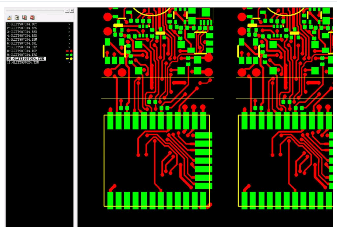
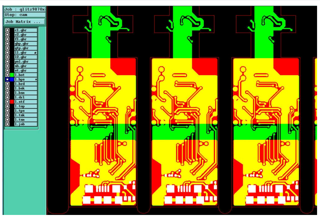
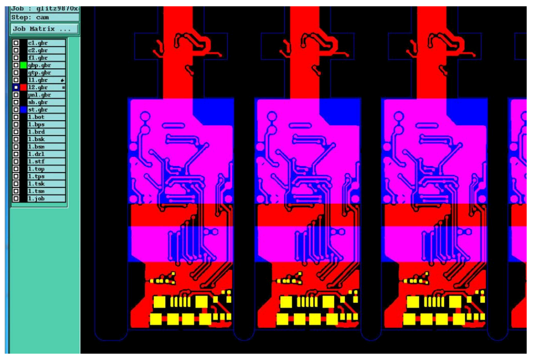
In above 3 pictures, it’s the exact design from customer. The first picture is the top circuit side review, which we can see there are some SMD components on the bottom (down side). The second picture is the stiffeners (yellow area) designed by customer for SMD components which should be assembled on the opposite side of top, the design is nearly correct, but there are some SMD PADs on bottom side (down side), which is covered by stiffeners, it will be a mistake to keep original design. The third picture is the modified design for stiffeners (blue area) which was canceled, the bottom stiffeners on the area have SMD components (in the picture 2). Now they are correct and can be moved to manufacturinng process (picture 3).
Capabilities
Payment Methods
Specials Price
Carriers
Support Hobbyist
Certificate
Customer Support
Follow Us
Tel: 1-905-339-2881
Email: sales@goldphoenixpcb.com , tech@goldphoenixpcb.com
Copyright Gold Phoenix PCB Co., Ltd. 2011 - 2025
Tel: 1-905-339-2881 Email: sales@goldphoenixpcb.com , tech@goldphoenixpcb.com
Quality Control System
|
Products/Service
|
Friendly Links
Copyright Gold Phoenix PCB Co., Ltd. 2011 - 2025


